My wife and I got three backyard chickens a few months ago. There was a lot of setup work initially, but we eventually settled into a routine that didn’t require much daily work. One pain point was waking up early enough to let the chickens out of their coop at a time they felt was reasonable, i.e., sunrise. We also didn’t have a way of letting them in and out of their coop if we were away from home.
This is the story of how I built an automatic chicken coop door controller that opens at sunrise and closes at sunset. This is the story of how I spent a lot of time automating a small part of chicken ownership. And then fixing, improving, and iterating on the door over and over again.
I went into this project viewing it as more of a learning opportunity than an opportunity to make my life more efficient. This project gave me the chance to integrate several skills I have been working on over the last several years, like software development and woodworking, while also diving into totally new areas to me like electrical engineering and mechanical engineering. If it weren’t for the learning opportunities I would have probably just purchased an existing offering like this.
Overview
- Order materials
- Solder board and button
- Wire the circuits
- Write the program
- Mount servo and assemble
Order materials
For this project I bought the following items:
| Quantity | Item | Cost |
|---|---|---|
| 1 | Arduino Nano Every | $13.00 |
| 1 | solderless breadboard with 400 pins | $8.99 |
| 1 | DS3231 RTC (real-time clock) | $10.99 |
| 1 | CR2032 3 Volt Lithium Coin Cell Battery | $6.05 |
| 1 | 20KG digital servo with metal gears and 270° rotation | $18.97 |
| 1 | 25T long servo horn | $9.98 |
| 1 | momentary push button | $8.89 |
| 1 | soldering kit | $9.99 |
| 10 | breadboard jumper wires | $5.79 |
| 1 | 19,200mAh rechargeable battery pack with no automatic low-voltage shutoff | $85.00 |
Note that the quantities above are what is required for this project but it was more economical to order some things in packs. The total cost for this project came to roughly $178, though some of that cost is offset by the leftover quantities from the order above.
I had also previously purchased the Arduino starter kit to prototype the controller but this wasn’t strictly necessary. Lastly, I used a few tools and materials I already owned, including a SawStop contractor table saw, drill and impact driver, a Kreg pocket hole jig system, a handful of Kreg pocket hole screws, wood star drive fasteners, a steel servo control rod, and some scrap wood.
Solder board and button
I got one of the smallest Arduino boards, the Arduino Nano Every, for this project because I didn’t need much memory or CPU for this project. I got my first soldering kit and soldered:
- the header pins to the Nano board
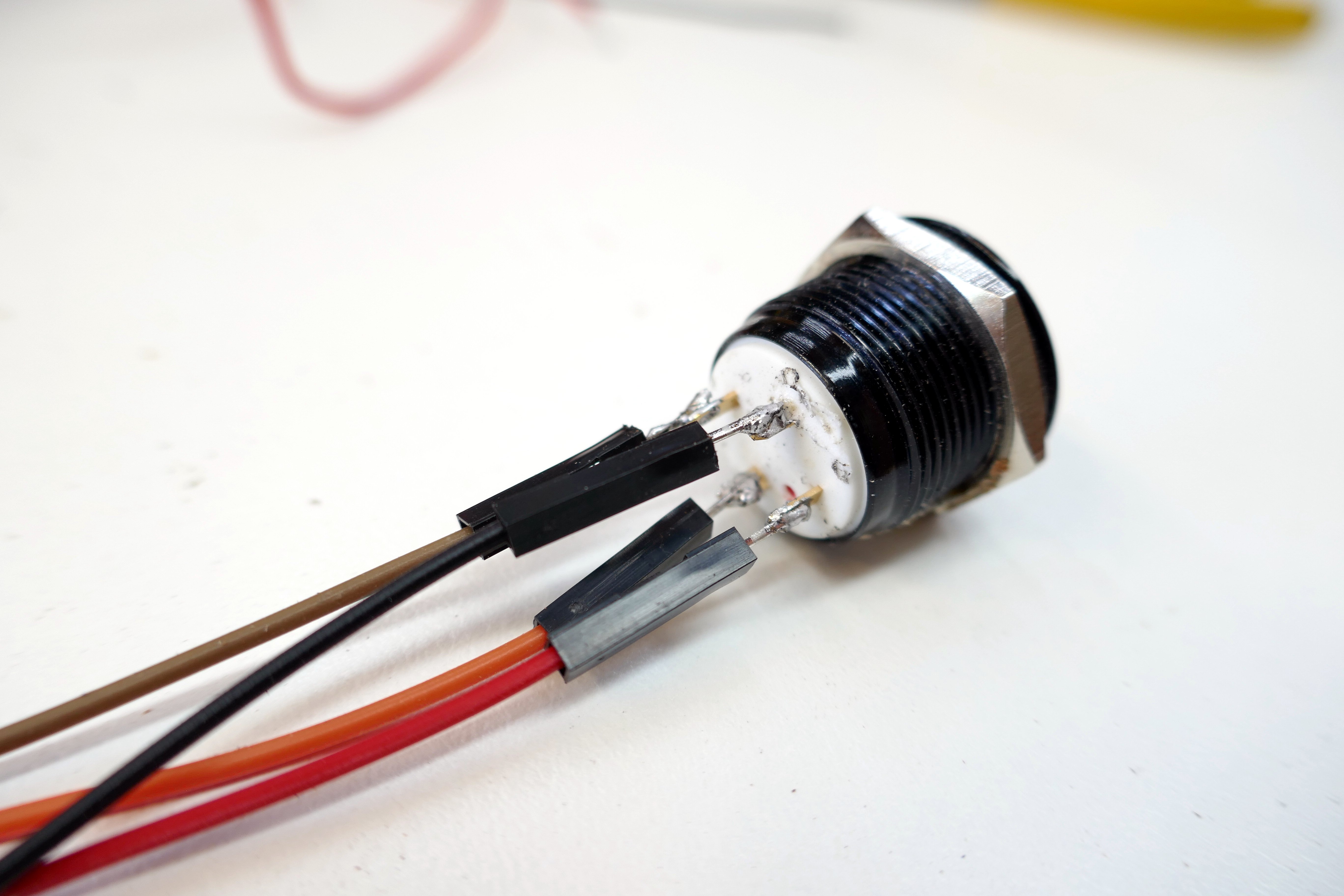
- wires to the momentary push button
Soldering the header pins
The first time I soldered the Nano board, I made the mistake of not soldering the header pins at a 90° angle to the board. Even worse, the two rows of header pins didn’t come out to the same non-right angle:
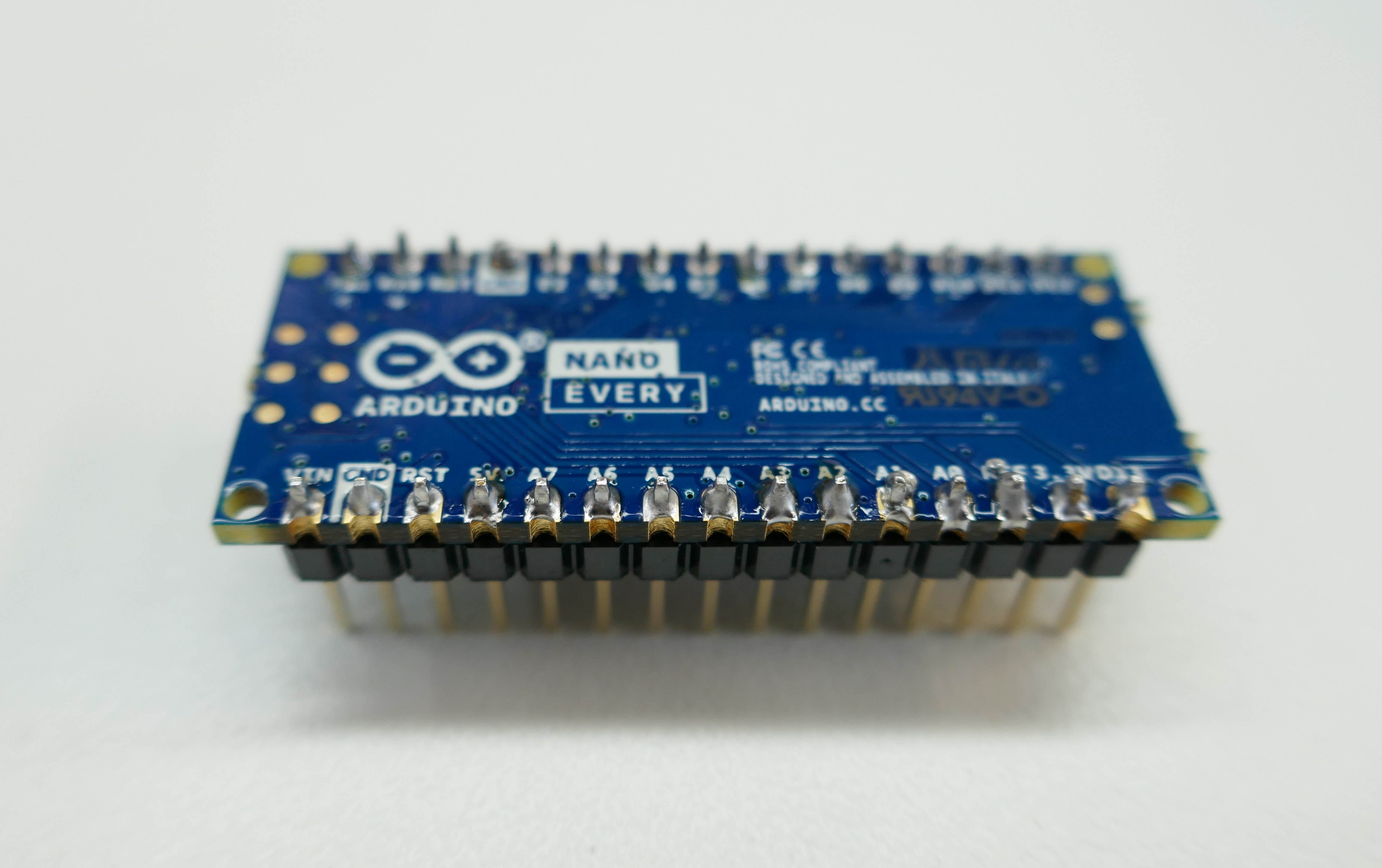
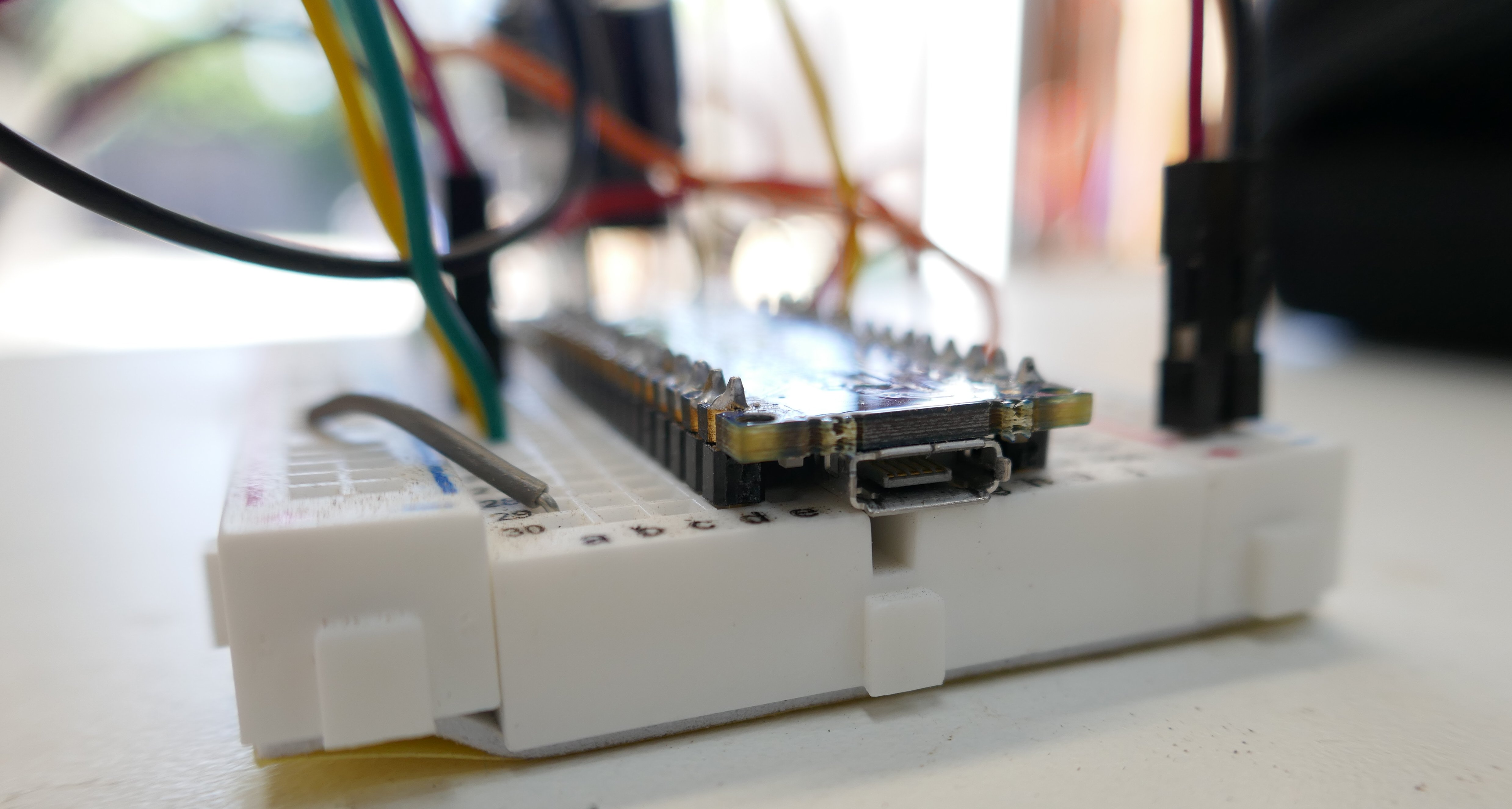
I fixed this by applying horizontal pressure to each pin while re-heating with the soldering iron until I was able to secure the Nano onto the breadboard:
Soldering the push button
The first time I soldered the momentary push button I did so with wires that came with the soldering kit but the individual strands that comprise the wire didn’t stick together after striping the insulation from the wire, which made inserting into the breadboard extremely frustrating since I had to connect these wires to the breadboard from an awkward position within the chicken coop (see pictures below).
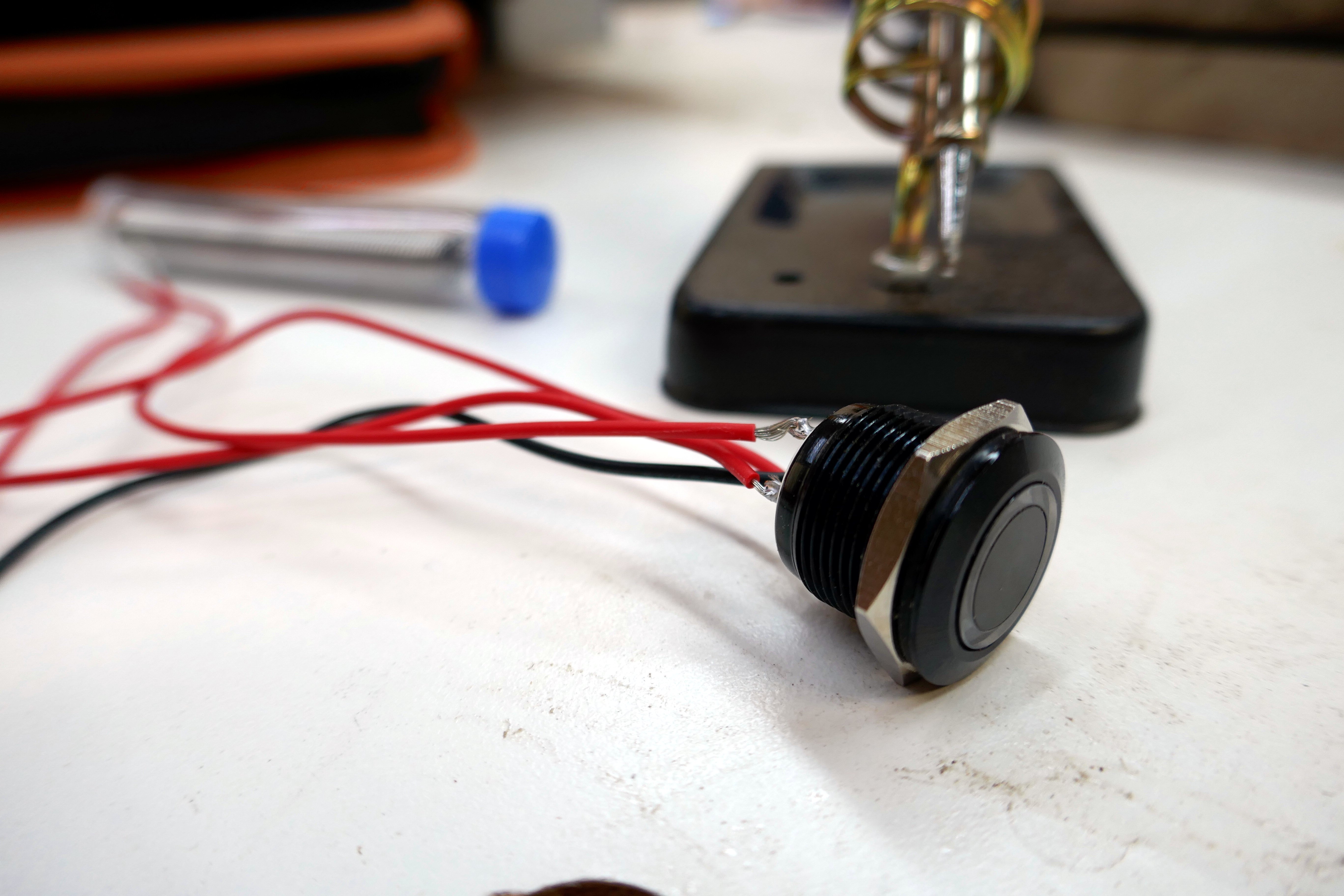
Because of this, I removed those wires and soldered breadboard male-to-male jumper wires instead. Pro tip: use distinctly colored wires, especially if you won’t have a full line of site to trace your wires to their destinations…
Wire the circuits
Wiring the circuits was the most straightforward part, though I certainly didn’t get it right the first time. Or the second time or the third time.
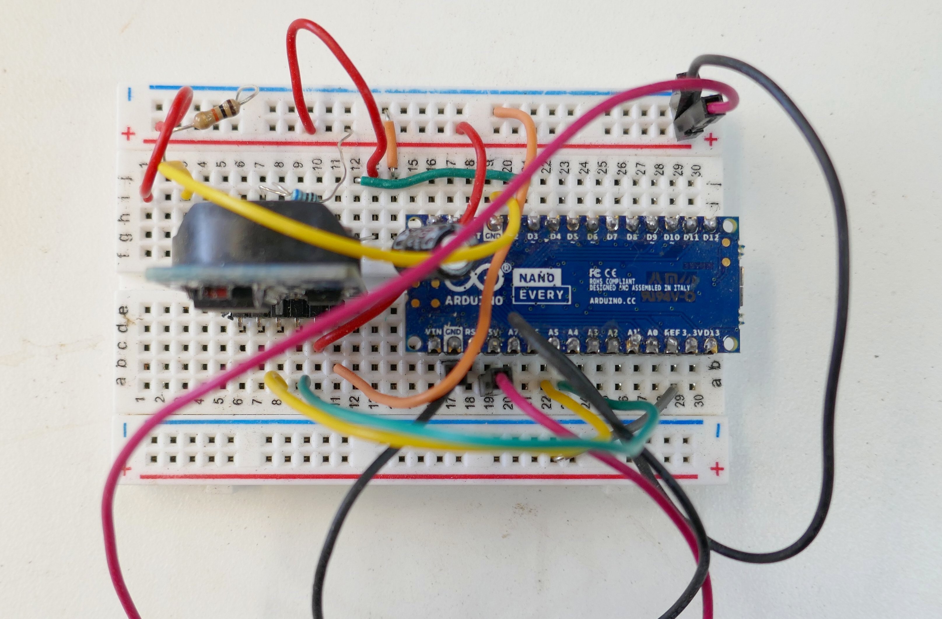
One notable debugging session came when upgrading my servo. I had initially wired my breadboard for the small servo that comes in the Arduino Uno starter kit, I later replaced this servo with a more powerful servo with metal gears. Relative to the old servo, the power line in the new servo was swapped in position with the control line. While I switched the corresponding 5v and pulse wires coming from the board, I forgot to move the anode in my decoupling capacitor to the new power circuit. It took me quite a while to diagnose this issue since I couldn’t immediately rule out other issues like a bad servo.
Write the program
Writing the program was the simplest part of this project, in part because I have much more software development experience than mechanical and electrical engineering. It’s been a while since I programmed in C++ so the trickiest part was remembering to add semi-colons after each line… My source code for this project can be found in this repo.
One thing I learned is that the complexity of debugging software is compounded when the software is coupled with hardware. I spent quite a bit of time trying to figure out why my program would hang at the line where it reads the current time from the RTC device upon initialization. I eventually figured out that adding a delay before this first RTC read solved this issue most of the time (but not all of the time). My current hypothesis is that the RTC boot time is highly variable and if the first read occurs before the RTC is ready then the program will hang.
Mount servo and assemble
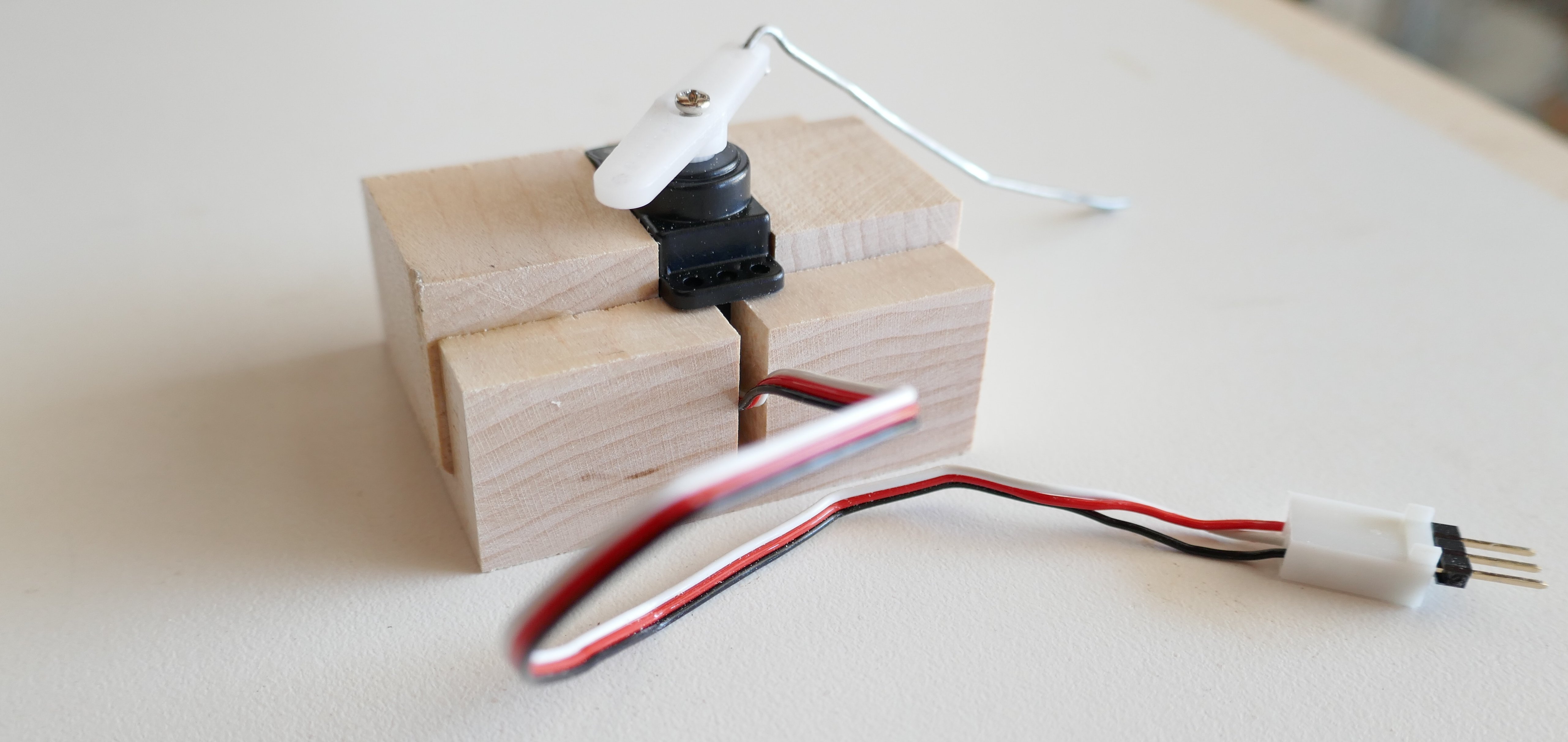
Another new challenge for me was figuring out how to mechanically move the door via servo rotational force. Initially, I set my 9g servo in a hard maple mounting block that I milled on my table saw and then used a paper clip as a control rod.
Not surprisingly, there were numerous issues with this approach, though each issue was solved fairly easily:
| Issue | Solution |
|---|---|
| the plastic servo gears broke after I pulled the door open to forcefully | buy a larger servo (20g) with metal gears |
| the paper clip snapped at the point where I had attached it to the door | use a steel control rod made for being a control rod |
| I split the mounting block with my fasteners since the servo mounting holes were so close to the edge of the dado I cut for the wire outlet | use plywood since multiple plies will help prevent splitting; also pre-drill before fastening |
Milling the new servo mounting block on my table saw:
I then built a small shelf from some pine scrap wood by cutting it to size on my table saw then fastening it to the coop with pocket screws. This was the result:
Finally, I connected the servo control arm to the servo horn on one end and to the chicken wire on the coop door on the other end. Et Voilà: